

Troubleshooting Common Broadcast Camera Issues: The Professional Studio Guide
Power cycling a broadcast camera chain during a live production isn't troubleshooting; it's gambling with on-air transmission. When an SDI return drops seconds before going live or a camera control unit loses tally communication, guesswork only prolongs expensive downtime. In high-pressure studio environments, successfully troubleshooting common broadcast camera issues demands systematic isolation rather than blind trial and error. Every engineer knows the sinking feeling of a flickering multiviewer feed, but chaotic cable-swapping often introduces new points of failure instead of resolving the original fault.
Mastering structured diagnostic workflows allows engineering teams to rapidly isolate and resolve signal loss, genlock sync failures, optical communication errors, and sudden thermal faults. Whether you're managing legacy triax, 12G-SDI, or SMPTE hybrid fiber chains, having a repeatable triage sequence protects your broadcast integrity. This guide delivers actionable inspection protocols for studio hardware, step-by-step signal-flow validation methods, and clear operational boundaries to determine when a fault can be solved on set or requires certified service center bench repair.
Key Takeaways
- Implement a structured four-tier triage framework to isolate faults between camera heads, transmission lines, and CCUs within seconds.
- Accelerate troubleshooting common broadcast camera issues by identifying the physical-layer markers of 12G-SDI cable loss versus SMPTE fiber link errors.
- Resolve lens communication faults, servo zoom shudder, and iris latency through proven pin-interface maintenance and back-focus calibration workflows.
- Protect production chains from DC rail overcurrent faults, intercom buzz, and thermal shutdowns under demanding live broadcast conditions.
- Establish clear operating thresholds to distinguish between immediate on-set remediation and certified service center bench repairs.
Establishing an On-Air Diagnostic Framework for Broadcast Cameras
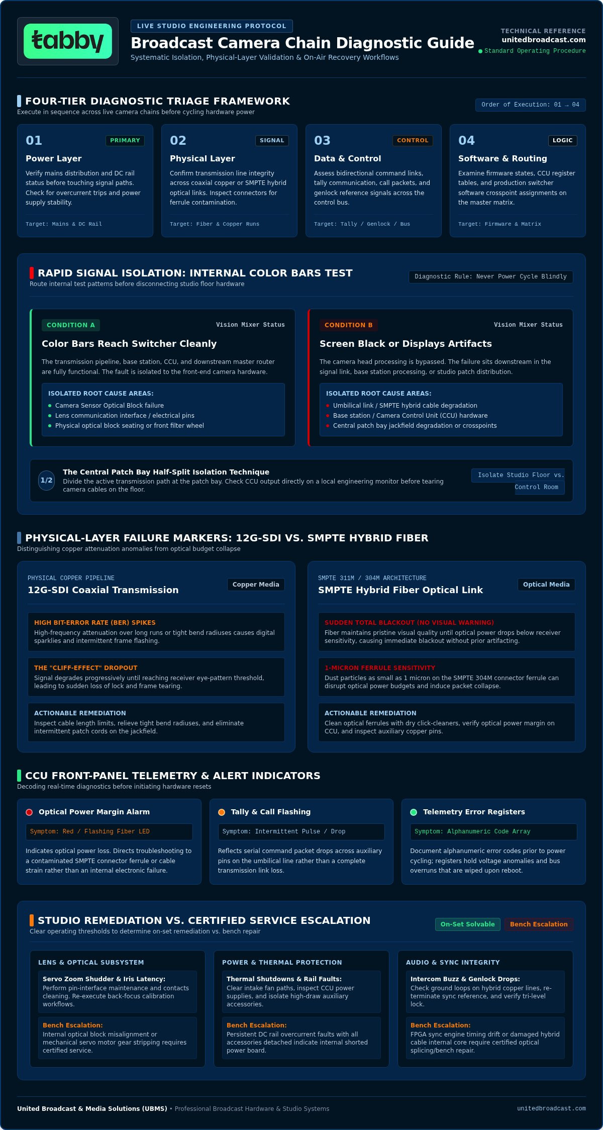
When a signal drops during a live transmission, panic is the enemy of recovery. Generic IT advice suggesting you reboot hardware blindly often wipes volatile log caches and prolongs dark time. Broadcast infrastructure requires an engineered response. Systematic troubleshooting common broadcast camera issues begins by executing a standard four-tier diagnostic triage across power, physical layer, data control, and software processing.
First, verify mains distribution and DC rail status before touching signal paths. Second, confirm physical-layer transmission integrity across coaxial copper or optical connections. Third, assess whether bidirectional command links, tally tallies, and genlock reference signals are communicating across the bus. Finally, examine firmware states and software crosspoint assignments. In high-tier production environments using professional video cameras, isolating whether a fault sits at the head, the umbilical link, or the base station determines whether recovery takes five seconds or fifteen minutes.
Before disconnecting any studio hardware, instruct the vision mixer or technical operator to route camera internal color bars. If color bars reach the production switcher cleanly, your sensor optical block or lens interface is compromised, while the umbilical run, base station, and downstream router remain healthy. If the screen remains black or displays digital artifacting, the failure sits downstream in the transmission chain, base station hardware, or CCU patch routing.
The Half-Split Technique in Multi-Camera Broadcast Chains
The half-split method isolates faults by dividing the active transmission path directly at the central patch bay. Instead of tearing apart camera cables on the studio floor, verify the base station output on a local engineering monitor. If the signal is absent at the CCU, swap the patch cord with a known functional spare to rule out jackfield degradation. Always inspect production switcher crosspoints and multiviewer pipeline inputs before concluding that physical camera hardware has failed.
Decoding Built-In Telemetry and Warning Indicators
Modern studio heads provide immediate operational feedback through viewfinder symbology and Camera Control Unit (CCU) front-panel indicators. Reading these alerts correctly prevents misdiagnosing the primary root cause when troubleshooting common broadcast camera issues under transmission pressure.
- Optical Power Margin Alarms: A red or flashing fiber LED on the CCU signals optical power loss, pointing directly to a contaminated SMPTE connector rather than an electronic system failure.
- Tally and Call Indicators: Intermittent flashing on call indicators usually reflects serial command packet drops across auxiliary pins rather than complete transmission loss.
- Telemetry Error Codes: Always document CCU alphanumeric error registers before initiating any hardware reset; these codes capture voltage anomalies and bus overruns that vanish after cycling power.
Executing an automated fallback routing salvage routine on the master router keeps clean feeds on air while technical crews resolve underlying physical link failures.
Diagnosing Video Signal Transmission and Genlock Synchronization Drops
Digital video transmission failures rarely present as clean, predictable outages. Instead, engineers battle intermittent frame flashing, digital sparklies, or sudden lock loss. In physical copper pipelines, high-frequency attenuation causes high bit-error rates (BER) in 12G-SDI runs, creating cliff-effect dropouts when cable lengths exceed specification or bend radiuses are violated. SMPTE hybrid fiber architectures behave differently. Optical links maintain pristine transmission until signal levels drop below receiver sensitivity thresholds, causing sudden, total blackout without visual warning.
Effective troubleshooting common broadcast camera issues across transmission lines requires inspecting physical media before adjusting electronic settings. Dust particles as small as one micron on a SMPTE 304M connector ferrule can disrupt optical budgets entirely, introducing severe packet drops across uncompressed video streams.
SMPTE 311M Hybrid Fiber and Triax Cable Troubleshooting
Always inspect optical end faces with a 400x ferrule microscope before mating connectors. Never dry-wipe contaminated pins; use an industry-standard wet-to-dry cleaning process with approved optical solvent to dissolve oils. Quantify attenuation using an optical power meter at 1310 nm and 1550 nm wavelengths. Normal link loss should remain below 1.5 dB across a typical studio run. If the base station refuses to supply power to the camera head, test the copper loop interlock line. SMPTE CCUs utilize a low-voltage sensing loop across pins 1 and 2 to ensure human safety before energizing the 240V DC auxiliary power rails.
Resolving Genlock, Phase, and PTP Timing Discrepancies
Reference mismatches cause disruptive frame tears and roll bars on production switchers. In baseband SDI workflows, an unlocked indicator points to invalid black burst or tri-level sync incoming feeds. Verify physical terminating resistors; a missing 75-ohm terminator on a looping genlock input reflects signal energy back into the distribution amplifier, corrupting timing across every daisy-chained unit.
For IP-based live productions operating under SMPTE ST 2110, timing errors manifest as Precision Time Protocol (PTP) domain mismatches. If a camera head drifts out of alignment, confirm that the grandmaster clock priority and PTP domain IDs match switch fabric profiles precisely. Integrating verified broadcast studio gear ensures infrastructure timing stability across mixed baseband and IP camera chains. If persistent synchronization or optical transmission anomalies continue across certified lines, our team can help you audit facility routing and link calibration through an engineering consultation.
Resolving Optical Issues, Lens Communication, and Sensor Artifacts
Optical anomalies and lens communication drops can derail a broadcast just as fast as a severed transmission line. When an iris stops responding to CCU commands or a servo drive begins tracking erratically, operators lose shot control instantly. Successfully troubleshooting common broadcast camera issues at the front of the chain requires isolating mechanical gear resistance from electronic interface failures and optical block misalignments.
Most communication dropouts trace back to the physical lens mount interface. Oxidation, recessed spring pins, or micro-debris on internal contacts interrupt serial data exchanges between the camera head and lens servos. This interruption prevents the CCU from reading focal length telemetry or driving motorized aperture rings. Addressing these faults systematically restores electronic control and image fidelity before going live.
Restoring Lens Mount Contact and Servo Control
Inspect the 12-pin Hirose connector and electronic mount contacts for bent pins, debris, or carbon buildup. Clean contact surfaces using a lint-free swab moistened with electronic-grade isopropyl alcohol, avoiding abrasive tools that strip gold plating. If servo zoom shudder occurs, check the mechanical clutch engagement. Recalibrate digital servo endpoints through the lens utility menu to clear potentiometer drift. For comprehensive mechanical servicing steps, consulting an authoritative cinema lens repair guide helps isolate internal drive belt tension faults from camera power delivery errors.
Correcting Back Focus and Optical Flange Depth
Back focus drift causes zoom lenses to lose sharpness across focal adjustments. When zooming out from tight to wide shots, a properly calibrated lens must hold optical tracking without manual refocussing.
- Test Setup: Position a high-contrast Siemens star chart at least three meters from the camera in a controlled lighting environment.
- Aperture Configuration: Open the iris completely to minimize depth of field, using neutral density filters to control exposure.
- Telephoto Alignment: Zoom completely into the target, establish precise focus using the focus barrel, and do not touch it again.
- Wide Adjustment: Zoom fully out to the widest angle, loosen the back focus locking screw, and rotate the optical flange ring until the star chart resolves sharply. Repeat this sequence twice before tightening the collar securely.
Eliminating Sensor Noise and Performing Pixel Masking
Sensor artifacts often mimic optical defects. High ambient operating temperatures induce thermal agitation in CMOS photo sites, producing stuck pixels and fixed pattern noise across dark areas. Execute an Auto Black Balance (ABB) routine only after camera electronics reach stable operating temperatures. Modern broadcast heads use this routine to calibrate sensor black levels and trigger automated pixel masking algorithms, re-mapping dead sensor elements seamlessly. When matching multi-camera studio looks, verify shutter frequency or activate Clear Scan to eradicate phase banding caused by LED backdrops.
Troubleshooting Power Drops, Thermal Instability, and Intercom Glitches
Live productions introduce aggressive electrical and environmental stresses that trigger sudden equipment failures. When a camera head abruptly cuts power on set, internal protection circuitry is often doing its job. Methodical troubleshooting common broadcast camera issues requires distinguishing between upstream power supply failures, accessory current overloads, and thermal shutdowns before swapping expensive components.
DC auxiliary outputs powering onboard monitors, wireless transmitters, and teleprompter displays share regulated internal rails. If combined current draws exceed factory limits, self-resetting solid-state fuses trip instantly to protect internal processor boards. Calculating total accessory power budgets prevents repeat shutdowns during critical cues.
Power Distribution and Thermal Management Protocols
Modern studio camera heads draw considerable power, and external accessories mounted on heavy studio rigs frequently overload 12V D-Tap and 4-pin Hirose ports. High torque motor spikes from wireless follow focus systems can easily exceed local rail amperage caps, dropping the camera head offline. Verify auxiliary load ratings and power secondary monitors from external block batteries when rigs exceed safe limits.
High ambient heat combined with clogged chassis filters leads to thermal throttling and sudden optical engine shutdowns. Inspect internal intake channels for dust accumulation and monitor diagnostic telemetry for fan RPM alerts. When cameras operate under harsh outdoor environments, maintaining clean airflow keeps processing temperatures within manufacturer tolerances. Production teams managing mobile broadcast operations can review robust power distribution architectures in our guide to OB van system integration.
Engineering Intercom and Tally Logic Failures
Intercom glitches and broken tally signaling disrupt floor operations just as severely as video loss. Buzzing or persistent ground hum on 4-wire engineering circuits usually stems from shield currents, ground potential differences, or unbalanced pin configurations across patch panels. Isolating matrix comms lines through audio balancing transformers removes common-mode noise without degrading audio intelligibility.
When on-air tally signaling fails, trace the complete logic path from production switcher to CCU GPIO interfaces:
- Dry Contact Verification: Check relay closures at the switcher frame using a basic multimeter continuity test to rule out vision mixer hardware faults.
- Optocoupler Isolation: Confirm that base station logic cards register contact closure across CCU pins 1 and 2 without ground leakage.
- IP Control Latency: In network-managed studios, verify that TSL tally protocol multicast streams are not blocked by switch IGMP querier misconfigurations.
Eliminating communication and power faults methodically keeps operators coordinated and protects complex studio chains during live multi-camera transmissions.
Preventative Maintenance Routines and Certified Service Escalation
Preventative engineering forms the bedrock of live production reliability. Structured pre-flight procedures prevent minor mechanical wear from transforming into catastrophic on-air outages. While field triage resolves operational misconfigurations, effective troubleshooting common broadcast camera issues requires knowing where field repair ends and precision bench servicing begins. Studio facilities that establish rigorous maintenance protocols experience significantly fewer transmission dropouts and extend hardware service lifecycles.
Optical purity and thermal headroom demand continuous upkeep. Optical blocks and internal prism assemblies attract airborne contaminants every time a lens changes on the studio floor. Scheduling regular sensor cavity inspections in controlled cleanroom conditions protects multi-camera channels from permanent optical degradation.
Daily Studio Pre-Flight Inspection Checklist
Conduct technical line-up procedures at least sixty minutes before active production to ensure all camera chains communicate properly across the master switcher fabric:
- Auxiliary Path Line-Up: Verify return video feeds 1 and 2, viewfinder display overlays, and prompter outputs independently from the main vision path.
- Mechanical Optical Inspection: Rotate internal neutral density (ND) and color correction (CC) optical filter wheels through every position, confirming the detent mechanism engages cleanly without flagging or physical binding.
- Iris and Master Pedestal Tracking: Match tracking responses across remote control panels (RCPs) by executing optical black balance and white balance calibration sequences simultaneously across all heads.
Engineers evaluating studio upgrades can benchmark hardware requirements against our detailed review in the professional video cameras guide. For complex live and hybrid environments that require turnkey multi-camera workflows and technical staging, partnering with seasoned production teams like Straight Street Event Services can help ensure rock-solid execution from signal distribution to final delivery.
When to Escalate to a Certified Broadcast Service Center
Certain failures cannot and should not be remediated on set. Attempting invasive teardowns on studio stages risks introducing permanent prism misalignment, moisture ingress, or static discharge to sensitive micro-circuitry, voiding factory warranties immediately.
Escalate to bench-level engineering when encountering physical prism delamination, persistent back-focus tracking error across multiple tested lenses, or intermittent mainboard power rail drops. Professional bench facilities utilize laser collimators, sub-micron optical alignment jigs, and cleanroom flow benches to calibrate high-end optical blocks safely. When preparing hardware for escalation, compile a comprehensive fault dossier containing CCU telemetry dump logs, operational ambient temperatures, exact lens configurations, and high-resolution frame captures of image anomalies. For factory-grade calibration, optical collimation, and diagnostic support, contact our certified engineering team.
Securing Studio Reliability Through Systematic Engineering
Maintaining on-air continuity requires moving away from reactive guesswork. Successful troubleshooting common broadcast camera issues relies on structured physical-layer inspection, disciplined daily line-up checks, and knowing precisely when field adjustments must yield to bench-level recalibration. When technical teams follow repeatable diagnostic frameworks, unexpected signal drops and synchronization errors stay isolated before they can compromise a live transmission.
Backing your facility with proven technical infrastructure ensures your control room and floor crew remain resilient under demanding production schedules. As an authorized service and repair center supporting major broadcast camera manufacturers, we bring decades of field experience supporting high-reliability national broadcast facilities, backed by a comprehensive inventory of replacement components, cables, and studio camera chains.
Equip your engineering staff with validated diagnostic protocols and dependable hardware support to keep every live broadcast sharp, fully synchronized, and transmission-ready.
Frequently Asked Questions
How do I fix intermittent video loss on a broadcast camera connected via SMPTE fiber?
Inspect and wet-dry clean the SMPTE 304M optical ferrules immediately. Microscopic debris causes signal attenuation to hover near the optical receiver's digital cliff limit, producing sudden frame drops. Use an optical power meter to confirm link loss stays below 1.5 dB across the line. If optical power levels test clean, examine the cable under gentle physical movement to isolate fractured internal glass fibers.
Why is my broadcast camera failing to lock to the studio genlock reference?
A missing 75-ohm termination resistor or an incorrect sync format setting is the usual culprit. If the camera doesn't detect incoming black burst or tri-level sync, it reverts to its internal free-run crystal clock. When troubleshooting common broadcast camera issues with genlock, verify the incoming sync signal using a waveform monitor and confirm that base station configuration matches facility timing standards.
What causes the zoom lens on my broadcast camera to lose focus when zooming out?
This issue indicates misaligned optical flange focal depth, commonly known as back focus. Mechanical shocks, temperature shifts, or lens swaps change the precise distance between the rear lens element and the camera sensor plane. Loosen the back focus locking screw on the lens, focus on a high-contrast chart at the telephoto extreme, and then adjust the back focus ring at wide angle until sharp.
How can I fix flicker or horizontal banding when shooting against LED volume walls?
Engage the camera's Clear Scan or fine electronic shutter mode to synchronize shutter speed with the LED processor's refresh rate. Standard fractional shutter angles drift out of phase with pulse-width modulation drivers inside LED panels. Incrementally tune the camera shutter decimal frequency until horizontal scan lines and color-roll artifacts disappear completely from both the viewfinder and engineering waveform monitors.
What is the correct procedure for performing a Black Balance on a broadcast camera?
Execute the Auto Black Balance (ABB) routine only after the camera reaches standard operational temperature, typically fifteen minutes after power-on. The camera head automatically closes its internal shutter mechanism, measures thermal dark current across the image sensor, and balances RGB pedestal levels. Regular ABB routines eliminate stuck pixels, suppress thermal sensor noise, and maintain matched master pedestal levels across multi-camera configurations.
How do I resolve audio hum or buzzing in the camera operator intercom headset?
Intercom hum typically stems from a ground loop between the studio base station, mains power, and camera chassis. Isolate the intercom audio lines using an inline 600-ohm audio isolation transformer to eliminate shield currents. Check that headset cabling runs away from high-voltage AC mains lines, and verify that the CCU matrix connection uses balanced 4-wire audio rather than an unbalanced line.
Can dirty optical connectors cause a total CCU power failure to the camera head?
Dirty optical fibers won't block power directly, but damaged electrical pins inside the SMPTE 304M connector will. SMPTE hybrid cables carry optical glass alongside copper conductors. If base stations detect an open circuit on the safety sensing loop due to debris or bent copper contacts, the CCU refuses to send high-voltage DC down the line. When troubleshooting common broadcast camera issues, always verify copper continuity alongside optical clarity.


